1 Introduction
The purpose is to read and write data using a DAQ device where we use Visual Studio and C#. We will exemplify by using a DAQ device from NI (previously National Instruments). We will use a DAQ device called USB-6008 (which is part of the USB-600x low-cost series). DAQ devices from NI use the NI-DAQmx driver. Examples shown will work on all DAQ devices from NI that are using the NI-DAQmx driver (which is many!). The principles used can also be applied on other DAQ hardware from other vendors.
Visual Studio/C# and DAQ (YouTube) + PowerPoint (PDF) - Exemplified using DAQ hardware and DAQmx from NI
2 Data Acquisition (DAQ)
A DAQ System consists of 4 parts:
- Physical input/output signals, sensors
- DAQ device/hardware (we will use NI USB-600x)
- Driver software (NI-DAQmx in our case)
- Your software application (Application software) – We will use Visual Studio/C#
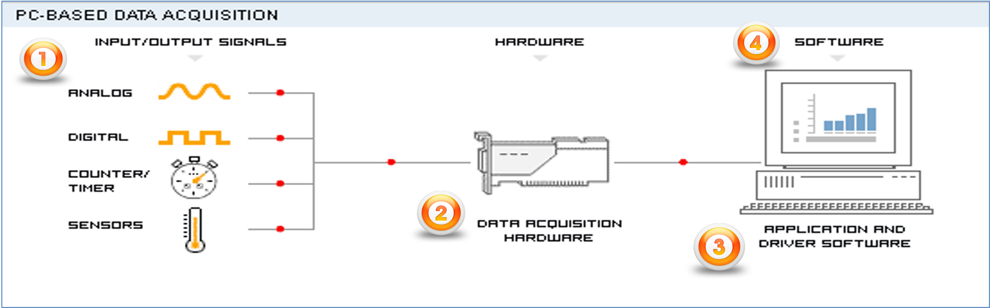
A DAQ device can be used to read data from Sensors, e.g., a Temperature Sensor (Analog In), or when we want to control something (Analog/Digital Out), e.g., a Heater, Pump, Valve, Light/Dimmer, etc. A DAQ device has typically Digital and Analog Channels.
4 different types of Signals:
- Analog Outputs (AO)
- Analog Inputs (AI)
- Digital Outputs (DO)
- Digital Inputs (DI)
Analog Channels typically have values between 0-5V/0-10V. Digital Channels are either 0/False (~0V) or 1/True (~2-5V).
3 NI DAQ Devices
We will use a DAQ device called USB-6008 (which is part of the USB-600x low-cost series). DAQ devices from NI use the NI-DAQmx driver.
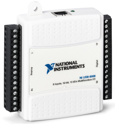
USB-6008 has been replaced with newer versions like USB-6000, USB-6001, USB-6002 and USB-6003, which have similar functionality as USB-6008 and they all work in the same manner, and they all use the NI-DAQmx driver.
Here you se another DAQ device Temperature Sensor TC-01with NI DAQmx using Visual Studio (YouTube) that is using the same NI-DAQmx driver.
NI-DAQmx
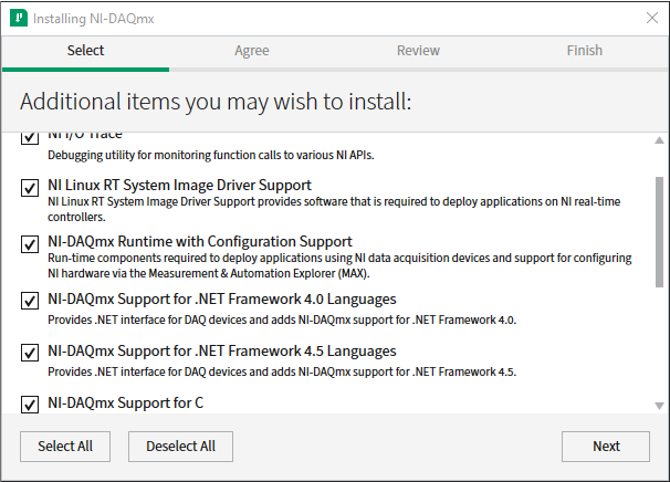
NI-DAQmx is the driver software you use to communicate with and control your DAQ devices made by NI. NI-DAQmx can be used with LabVIEW, Visual Studio/C#, Python, MATLAB, etc. NI-DAQmx can be downloaded for free (but you need of course to buy a NI-DAQmx compatible DAQ device if you don’t have one already).
NI-DAQmx can be downloaded from: www.ni.com/downloads
Make sure to add support for Visual Studio/.NET during installation of the NI-DAQmx software.
Measurement & Automation Explorer (MAX)
MAX is an application that automatically installs with the NI-DAQmx driver. With MAX, you can configure your NI hardware. MAX informs other programs which devices you have in your system and how they are configured.

NI-DAQmx Simulated Devices
If you don’t have a real DAQ device, you can create a Simulated Device.
To create an NI-DAQmx simulated device using MAX, complete the following steps:
- Right-click Devices and Interfaces and select Create New.
- A dialog box prompts you to select a device to add. Select Simulated NI-DAQmx Device or Modular Instrument and click Finish.
- Then you can select the DAQ device you want to simulate,
A Simulated Device will appear with a yellow icon in MAX. Now you can use it in LabVIEW, C#, etc.
5 Visual Studio/C# Code Examples
Note! NI-DAQmx is so far not supported for .NET 5 or higher, so you need to use the Windows Forms App (.NET Framework) Template and then select .NET Framework 4.x.
Next you need to add the reference NationalInstruments.DAQmx.dll by right-clicking in the Solution Explorer and select "Add Reference". This dll is installed by the NI-DAQmx driver and are typically installed within C:/Program Files (x86)/National Instruments/..
Here some basic code examples will be presented. Different Analog Outputs (AO), Analog Inputs (AI), Digital Outputs (DO) and Digital Inputs (DI) examples will be presented below.
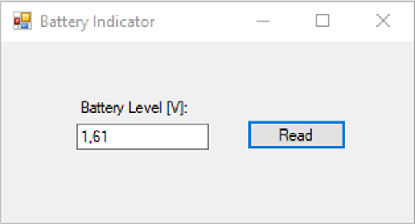
5 Battery Indicator (Analog In) Example
We start with a basic Example just reading the Voltage Value from a 1.5V battery that is connected to the DAQ device.
Analog In Battery Example with NI DAQmx using Visual Studio (YouTube)
Wiring:
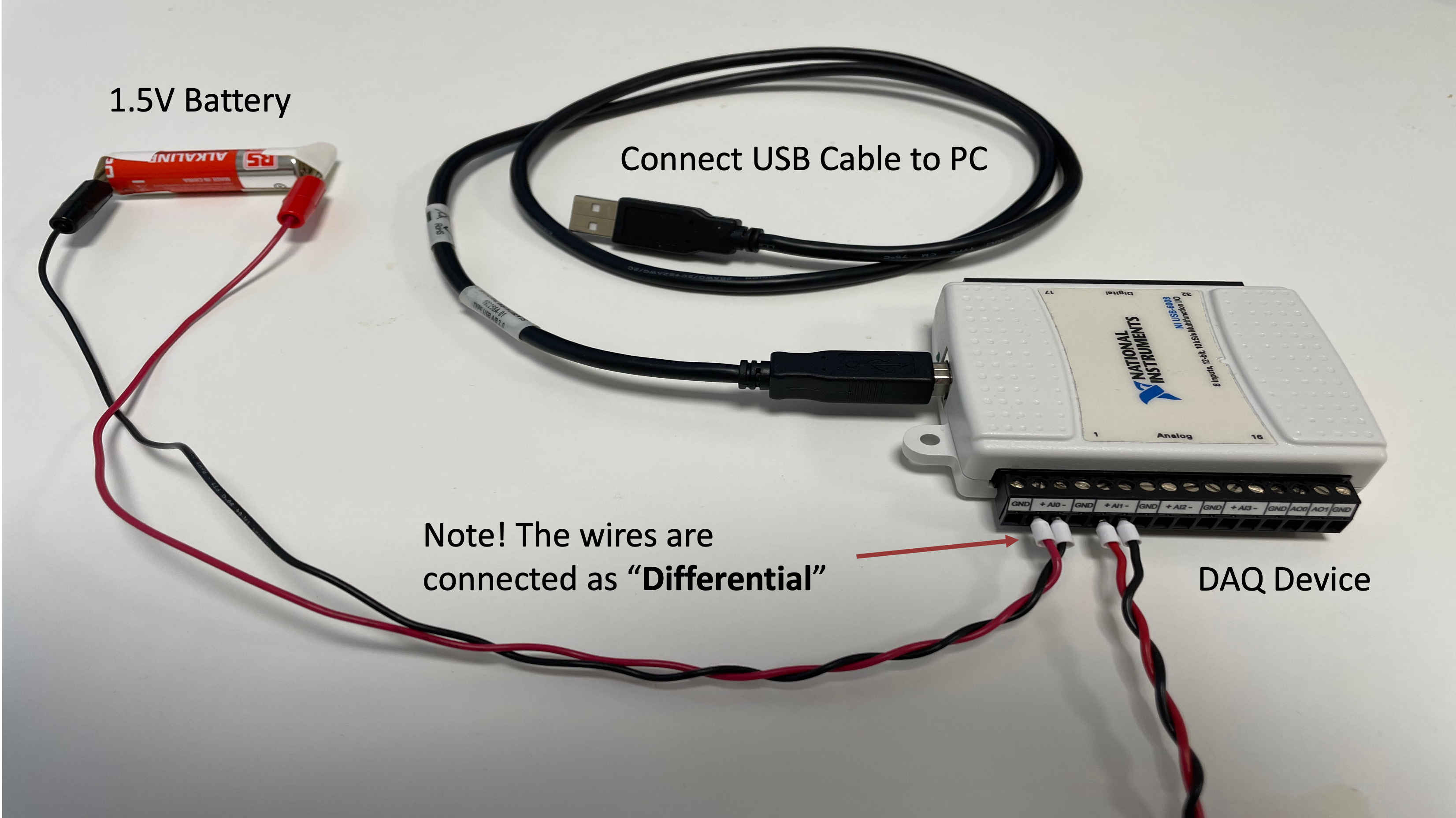
Make sure to read the User Guide and Specifications for USB-6008 and USB-6008 Pinout.
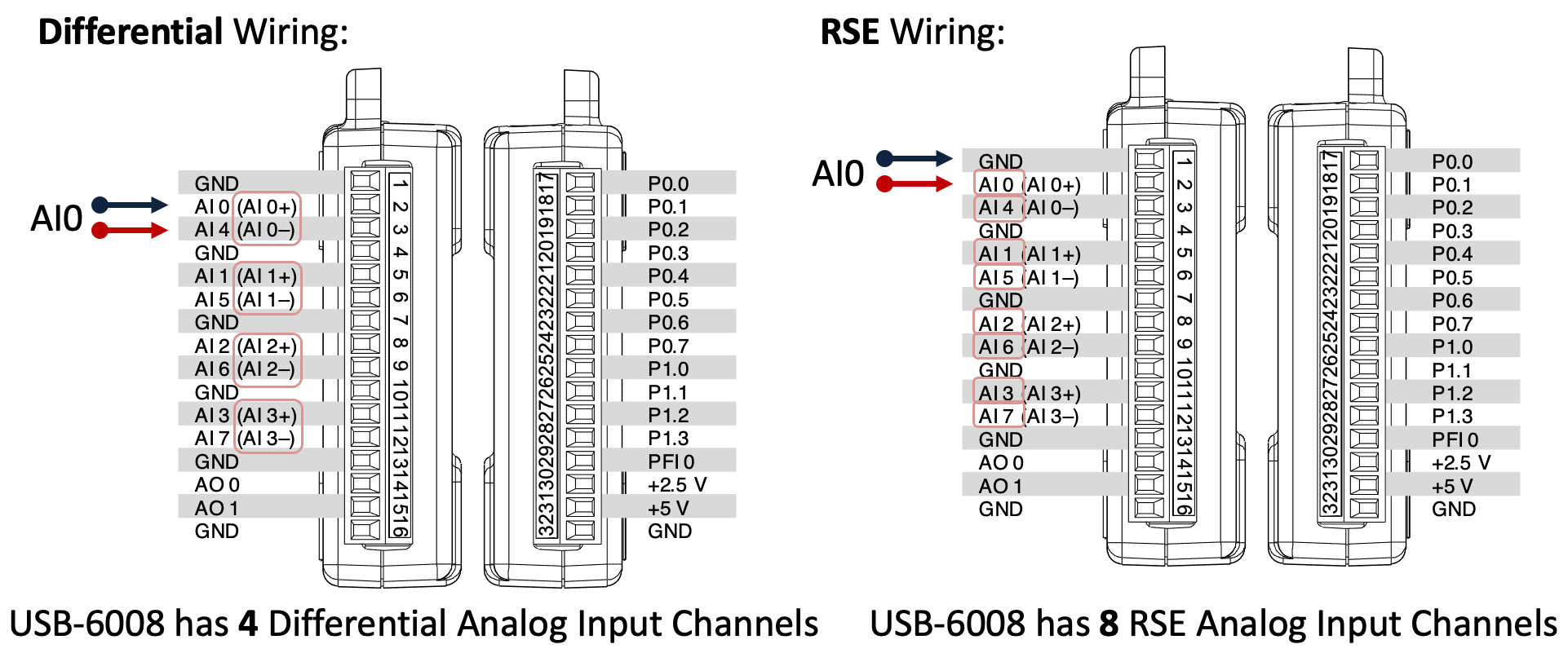
Below you see the Differential wiring vs. RSE wiring:
Below you see the main code needed in order to initialize the DAQ device and read a single Analog Input value:
..
using NationalInstruments.DAQmx;
..

Task analogInTask = new Task();

AIChannel myAIChannel;

myAIChannel = analogInTask.AIChannels.CreateVoltageChannel(
     "dev1/ai0",
     "myAIChannel",
     AITerminalConfiguration.Differential,
     0,
     5,
     AIVoltageUnits.Volts
     );

AnalogSingleChannelReader reader = new AnalogSingleChannelReader(analogInTask.Stream);

double voltage = reader.ReadSingleSample();
..
For the TerminalConfiguration we can choose between "RSE" and "Differential". We have used Differential wiring in this example.
The device name is "dev1", which is the default name, but the name can be changed from the MAX software.
We use the ReadSingleSample() method in order to read a voltage value from the DAQ device.
Final Application
In this basic example the DAQ code is put into the Button Click Event Handler. Here you see the entire code (Form1.cs):
using System;
using System.Windows.Forms;
using NationalInstruments.DAQmx;

namespace BatteryIndicator
{
    public partial class Form1 : Form
    {
        public Form1()
        {
            InitializeComponent();
        }

        private void btnGetData_Click(object sender, EventArgs e)
        {
            Task analogInTask = new Task();

            AIChannel myAIChannel;

            myAIChannel = analogInTask.AIChannels.CreateVoltageChannel(
                "dev1/ai0",
                "myAIChannel",
                AITerminalConfiguration.Differential,
                0,
                5,
                AIVoltageUnits.Volts
                );

            AnalogSingleChannelReader reader = new AnalogSingleChannelReader(analogInTask.Stream);

            double batteryLevel = reader.ReadSingleSample();

            txtBatteryLevel.Text = batteryLevel.ToString("0.00");
        }
    }
}
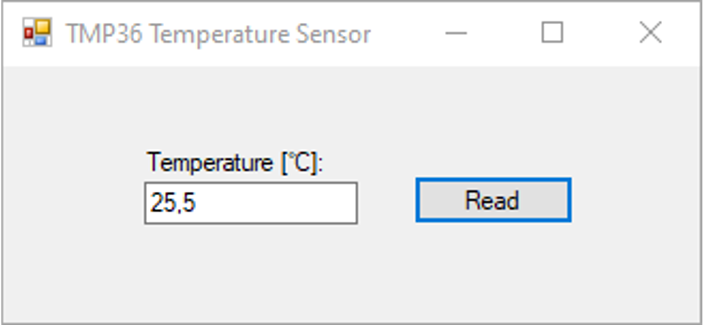
6 TMP36 Temperature Sensor Example (Analog In)
In this example we will use a TMP36 Temperature Sensor and read from the DAQ device and calculate the Temperature value in degrees Celsius.
TMP36 Temperature Sensor Example with NI DAQmx using Visual Studio (YouTube)
TMP36 Temperature Sensor
TMP36 provides a voltage output that is linearly proportional to the temperature in degrees Celsius. It has an accuracy of ±1°C at +25°C and ±2°C in the −40°C to +125°C temperature range. For more details, see the TMP36 Datasheet.
Here you see the relationship between voltage and the temperature in degrees Celsius:
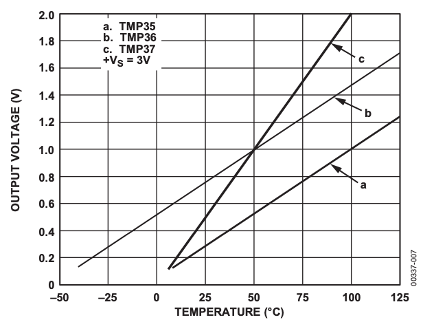
The figure above is from the TMP36 Datasheet.
Formula for converting from Voltage to Temperature in Degrees Celsius: y = 100x - 50, where x is the value read from the DAQ device in voltage.
Wiring:
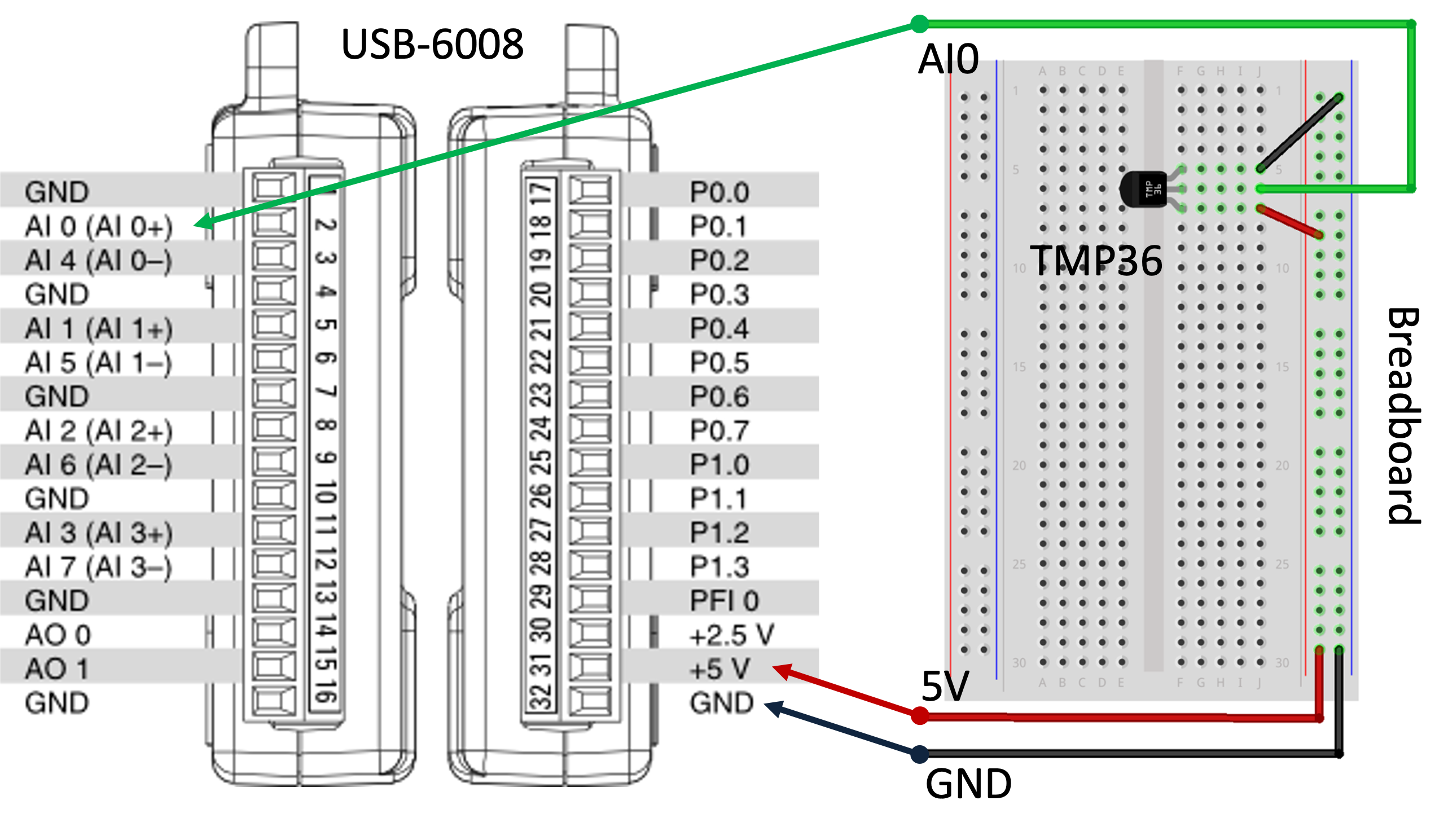
Note! The wires are connected as "RSE".
We can create a method called ReadTemperature() where we put all the DAQ spesific code:
double ReadTemperature()
{
   Task analogInTask = new Task();

   AIChannel myAIChannel;

   myAIChannel = analogInTask.AIChannels.CreateVoltageChannel(
        "dev1/ai0",
        "myAIChannel",
        AITerminalConfiguration.Rse,
        0,
        5,
        AIVoltageUnits.Volts
        );

   AnalogSingleChannelReader reader = new AnalogSingleChannelReader(analogInTask.Stream);

   double voltage = reader.ReadSingleSample();

   double temperature;

   temperature = 100 * voltage - 50; //Convert from Voltage to Temperature

   return temperature;
}
Final Application
Here you see the entire code for this example (Form1.cs):
using System;
using System.Windows.Forms;
using NationalInstruments.DAQmx;

namespace TMP36
{
    public partial class Form1 : Form
    {
        public Form1()
        {
            InitializeComponent();
        }

        private void btnReadTemperature_Click(object sender, EventArgs e)
        {
            double temperature;

            temperature = ReadTemperature();

            txtTemperature.Text = temperature.ToString("0.0");
        }

        double ReadTemperature()
        {
            Task analogInTask = new Task();

            AIChannel myAIChannel;

            myAIChannel = analogInTask.AIChannels.CreateVoltageChannel(
                "dev1/ai0",
                "myAIChannel",
                AITerminalConfiguration.Rse,
                0,
                5,
                AIVoltageUnits.Volts
                );

            AnalogSingleChannelReader reader = new AnalogSingleChannelReader(analogInTask.Stream);

            double voltage = reader.ReadSingleSample();

            double temperature;

            temperature = 100 * voltage - 50; //Convert from Voltage to Temperature

            return temperature;
        }
    }
}
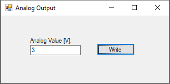
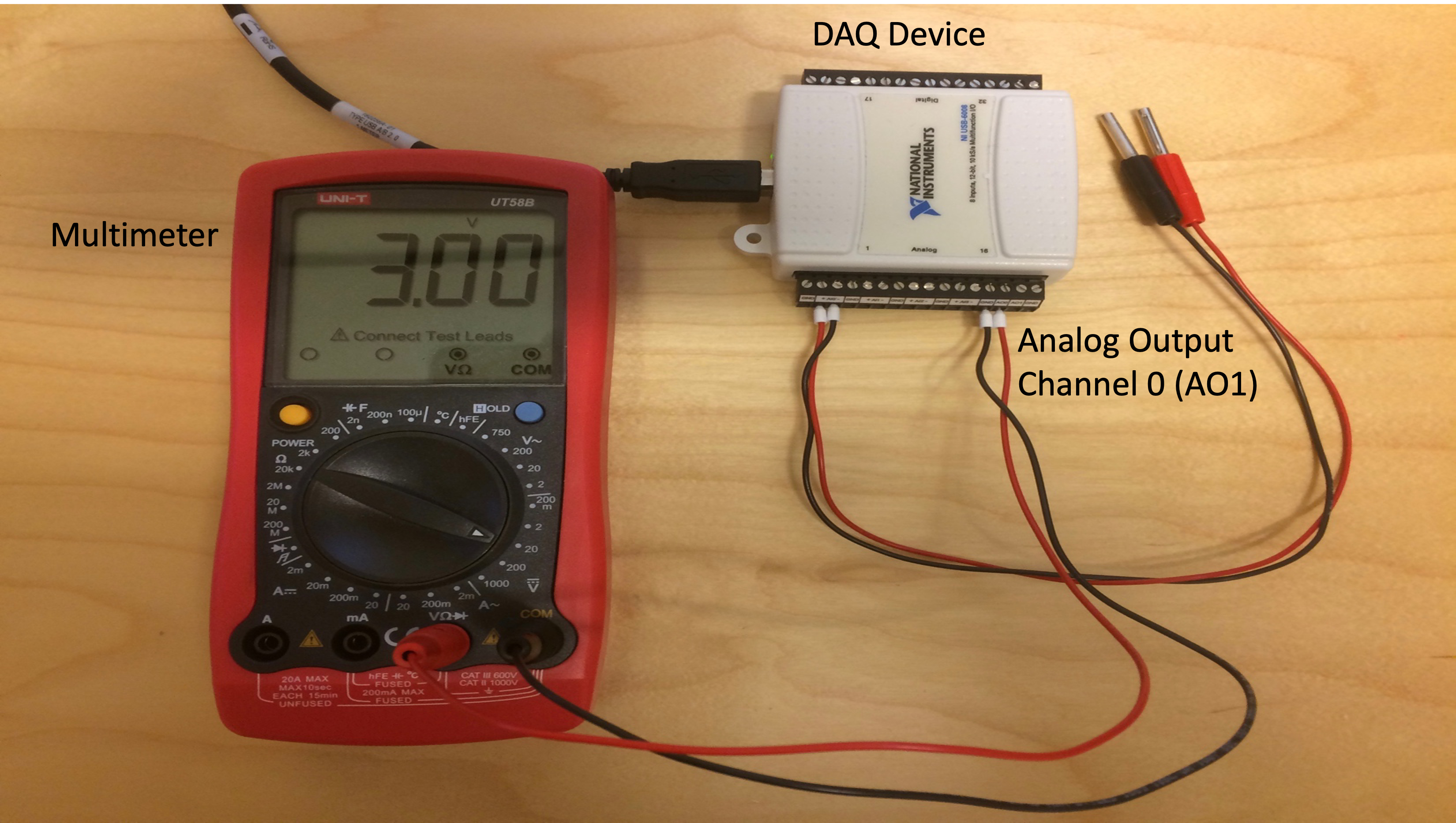
7 Analog Out
This Analog Out Example write a Value to the Analog Out 0 Channel (AO0) on the DAQ device. We can connect a Multimeter to see if the Application works as expected.
Analog Out Example with NI DAQmx using Visual Studio (YouTube)
Physical Wiring:
Basic Analog Out code:
Task analogOutTask = new Task();
AOChannel myAOChannel;
myAOChannel = analogOutTask.AOChannels.CreateVoltageChannel(
   "dev1/ao0",
   "myAOChannel",
   0,
   5,
   AOVoltageUnits.Volts
   );

AnalogSingleChannelWriter writer = new AnalogSingleChannelWriter(analogOutTask.Stream);

double analogDataOut = 3;
writer.WriteSingleSample(true, analogDataOut);
Final Application
Code for final Analog Out Application (Form1.cs):
using System;
using System.Windows.Forms;
using NationalInstruments.DAQmx;

namespace AnalogOut
{
    public partial class Form1 : Form
    {
        public Form1()
        {
            InitializeComponent();
        }

        private void btnWriteAnalogData_Click(object sender, EventArgs e)
        {
            Task analogOutTask = new Task();
            AOChannel myAOChannel;
            myAOChannel = analogOutTask.AOChannels.CreateVoltageChannel(
            "dev1/ao0",
            "myAOChannel",
            0,
            5,
            AOVoltageUnits.Volts
            );
            AnalogSingleChannelWriter writer = new AnalogSingleChannelWriter(analogOutTask.Stream);
            double analogDataOut;
            analogDataOut = Convert.ToDouble(txtAnalogVoltage.Text);
            writer.WriteSingleSample(true, analogDataOut);
        }
    }
}
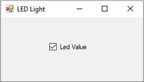
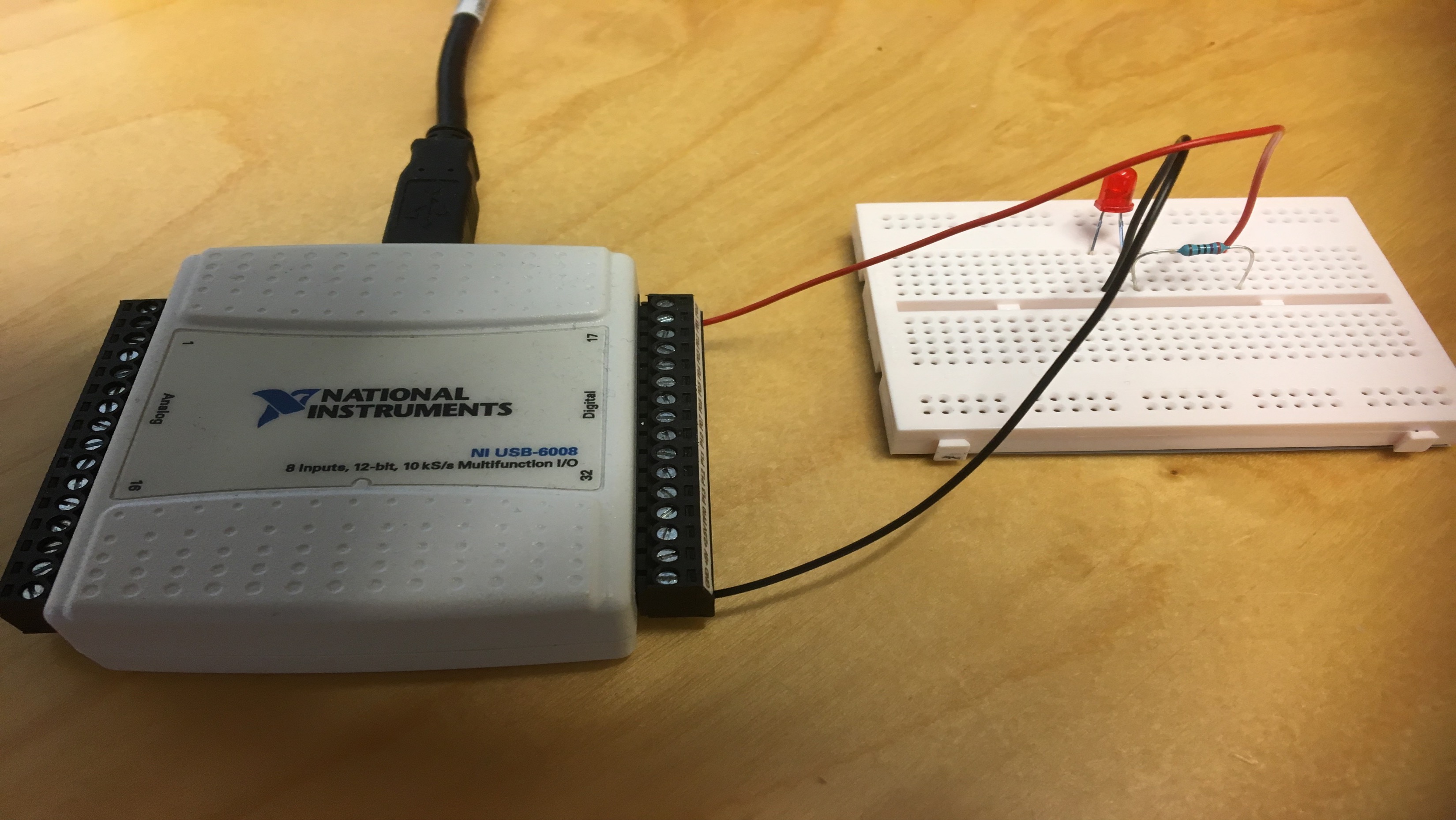
8 LED Example (Digital Out)
This Digital Out Example writes a Value to the Digital Out Port 0, Line 0 on the DAQ device. We can connect a Multimeter to see if the Application works as expected or we can connect a LED, etc.
LED Example with NI DAQmx using Visual Studio (YouTube)
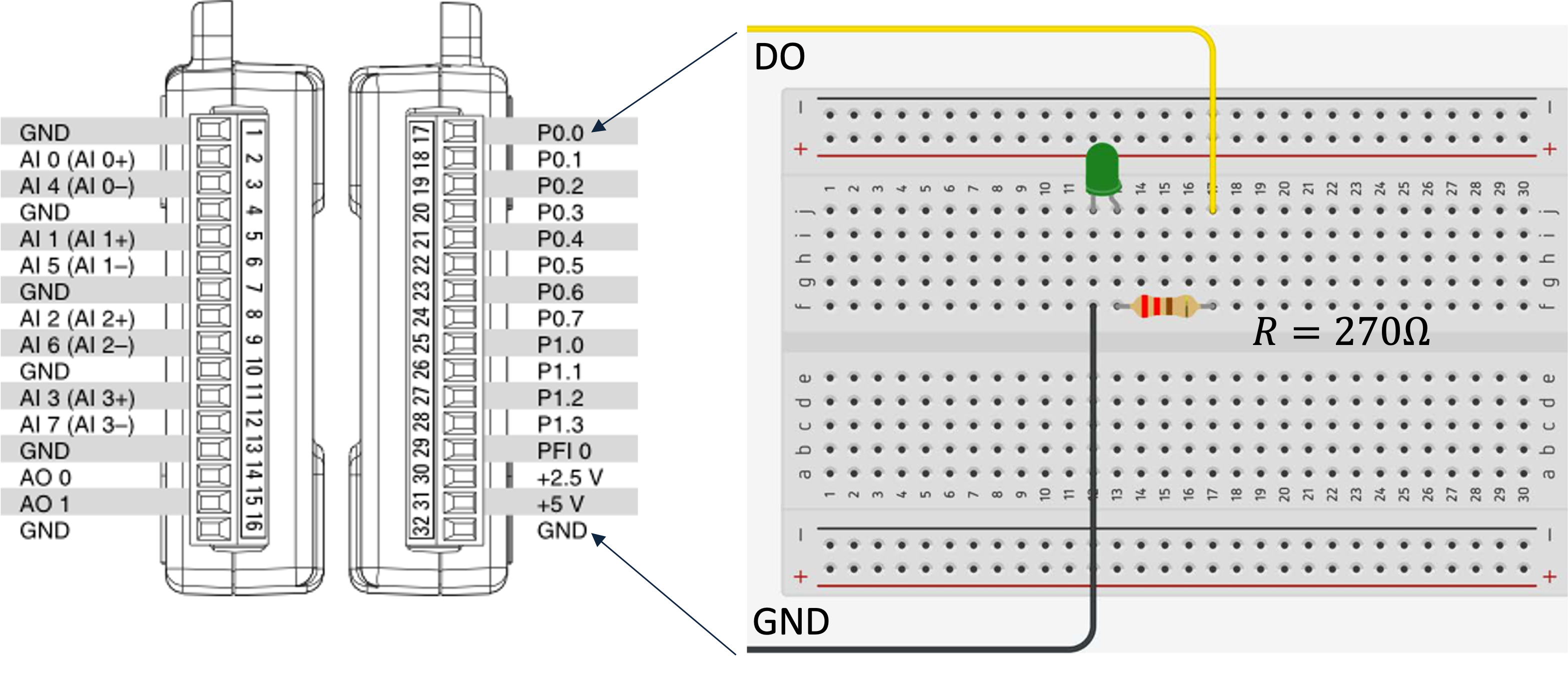
Physical Wiring:
Wiring Shema:
Basic Digital Out Code:
void LedLight(bool led)
{
     Task digitalOutTask = new Task();

     digitalOutTask.DOChannels.CreateChannel("dev1/Port0/line0",
                   "myDAChannel",
                   ChannelLineGrouping.OneChannelForEachLine);

     DigitalSingleChannelWriter writer = new
                    DigitalSingleChannelWriter(digitalOutTask.Stream);

     writer.WriteSingleSampleSingleLine(true, led);
}
Final Application
Code for final Digital Out Application (Form1.cs):
using System;
using System.Windows.Forms;
using NationalInstruments.DAQmx;

namespace LEDEx
{
    public partial class Form1 : Form
    {
        public Form1()
        {
            InitializeComponent();
        }

        private void checkBox1_CheckedChanged(object sender, EventArgs e)
        {
            bool led = false;

            if (checkBox1.Checked)
                led = true;
            else
                led = false;

            LedLight(led);
        }


        void LedLight(bool led)
        {
            Task digitalOutTask = new Task();

            digitalOutTask.DOChannels.CreateChannel("dev1/Port0/line0",
                                "myDAChannel",
                                ChannelLineGrouping.OneChannelForEachLine);

            DigitalSingleChannelWriter writer = new DigitalSingleChannelWriter(digitalOutTask.Stream);

            writer.WriteSingleSampleSingleLine(true, led);
        }
    }
}
Multiple LEDs Example
The basic LED example above use only one digital output, here you see a basic example with multiple Digital Outputs:
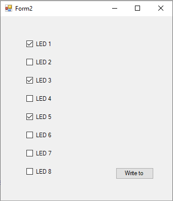
If you don’t have 8 LEDs, use a Multimeter to check the voltage value on the Digital Output Channels on the DAQ Device
Multiple LEDs Code Example:
using System;
using System.Windows.Forms;
using NationalInstruments.DAQmx;

namespace LEDApp
{
    public partial class Form2 : Form
    {
        public Form2()
        {
            InitializeComponent();
        }
        private void btnWriteDaq_Click(object sender, EventArgs e)
        {
            Task digitalOutTask = new Task();

            digitalOutTask.DOChannels.CreateChannel("dev1/Port0/line0:7",
                          "myDAChannel", ChannelLineGrouping.OneChannelForAllLines);

            DigitalSingleChannelWriter writer = new DigitalSingleChannelWriter(digitalOutTask.Stream);

            bool[] dataArray = new bool[8];
            dataArray[0] = chkLed1.Checked;
            dataArray[1] = chkLed2.Checked;
            dataArray[2] = chkLed3.Checked;
            dataArray[3] = chkLed4.Checked;
            dataArray[4] = chkLed5.Checked;
            dataArray[5] = chkLed6.Checked;
            dataArray[6] = chkLed7.Checked;
            dataArray[7] = chkLed8.Checked;

            writer.WriteSingleSampleMultiLine(true, dataArray);
        }
    }
}
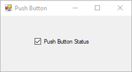
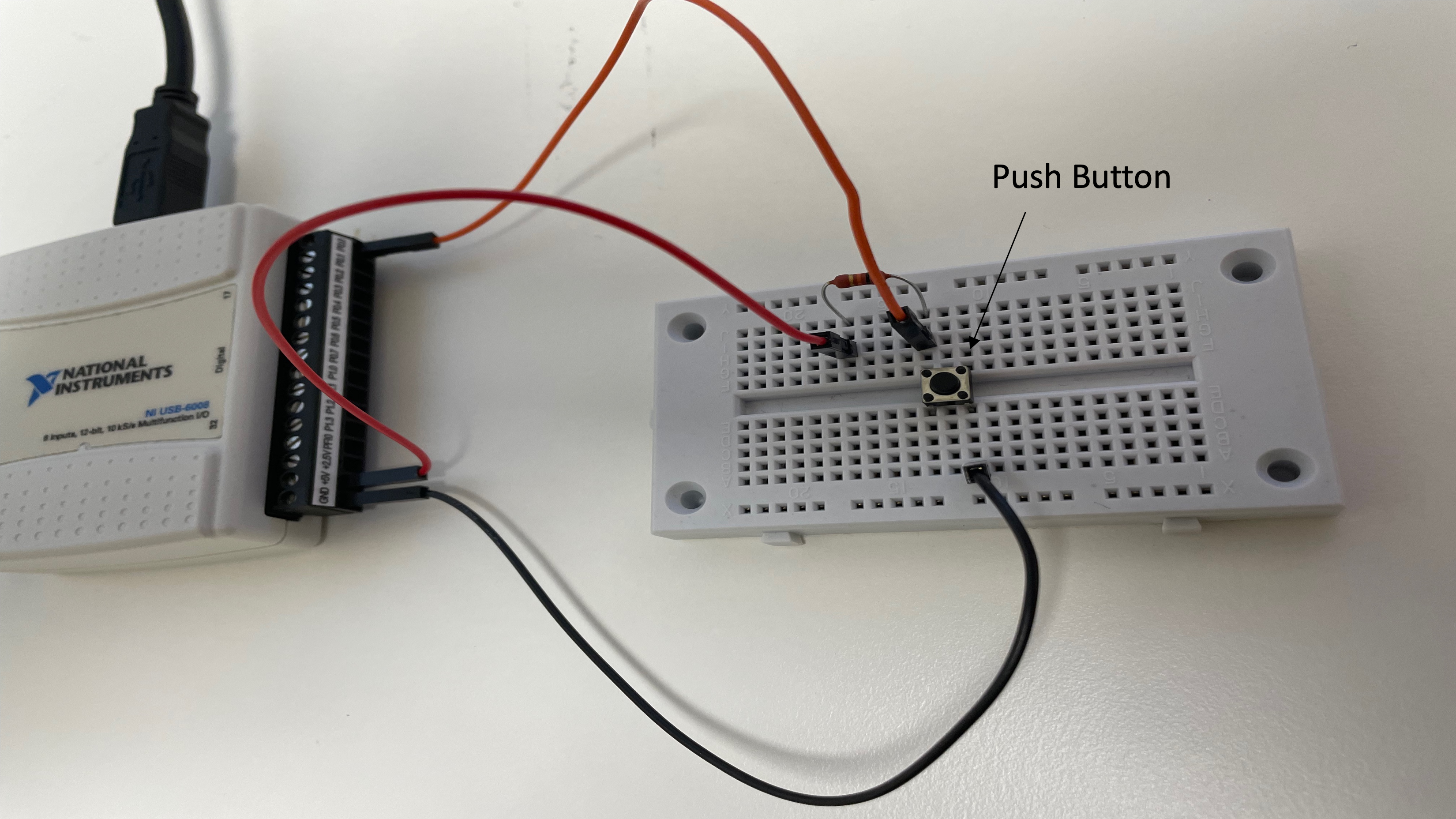
9 Push Button Example (Digital In)
This Digital In Example shows how we can use a Push Button to set a Digital In to be False/Low (0V) or True/High (5V).
Push Button Example with NI DAQmx using Visual Studio (YouTube)
Physical Wiring:
Wiring Schema:
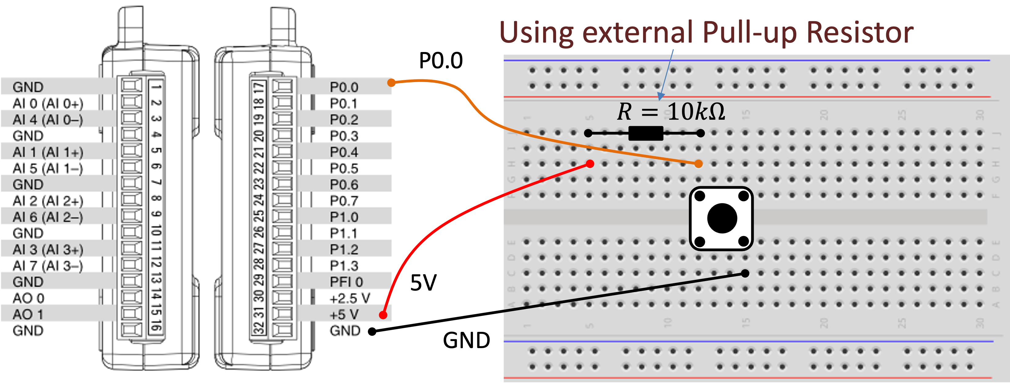
Pull-up Resistor
Why do we need a pull-up or pull-down resistor in the circuit? If you disconnect the digital I/O pin from everything, it will behave in an irregular way. This is because the input is "floating" - that is, it will randomly return either HIGH or LOW. That's why you need a pull-up or pull-down resistor in the circuit.
Below we see how the cuircuit with a Pull-up Resistor is working:
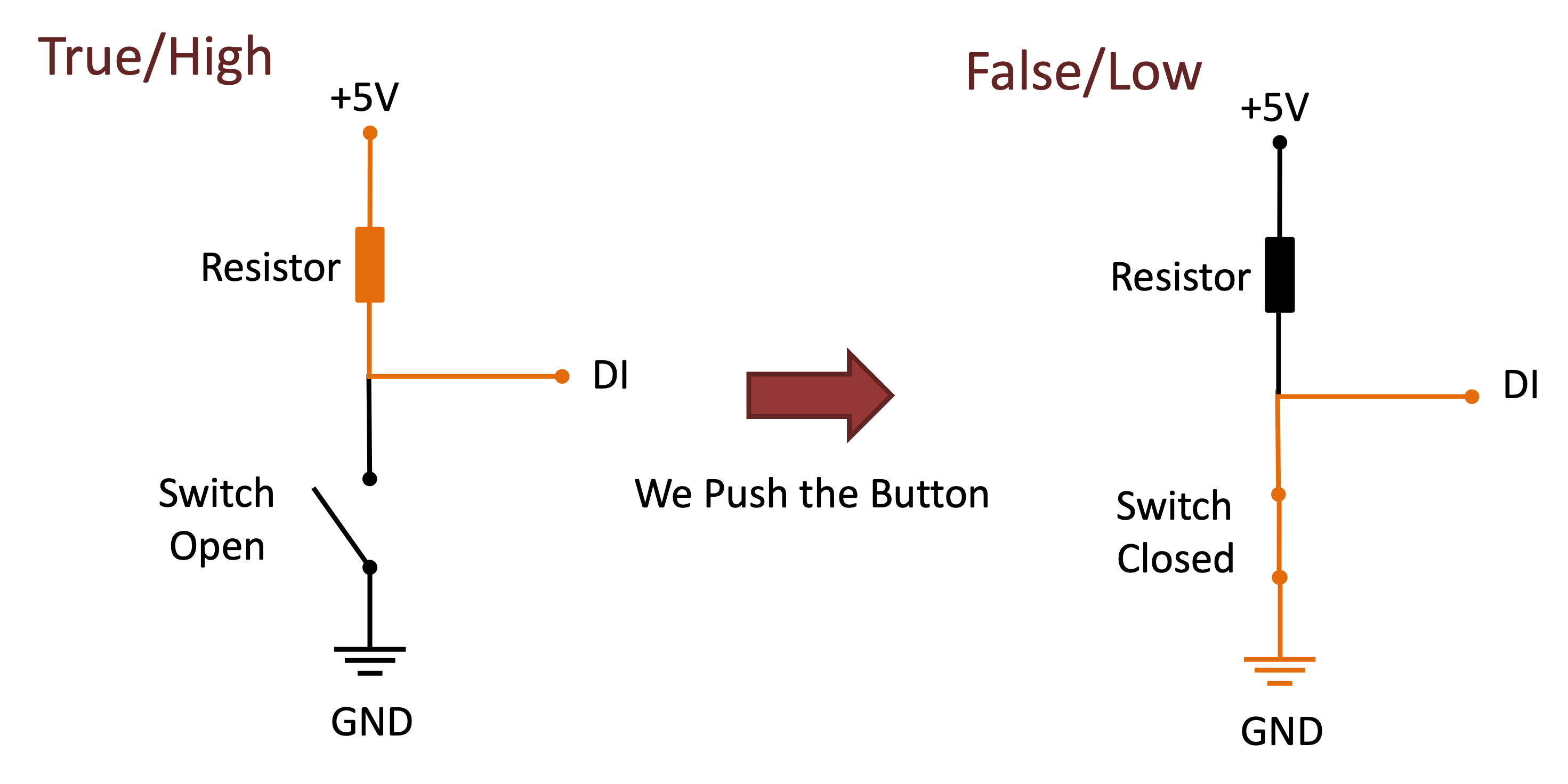
When the pushbutton is open (unpressed) there is a connection between 5V and the DI pin. This means the default state is True (High). When the button is closed (pressed), the state goes to False (Low).
Basic Digital In Code:
Task digitalInTask = new Task();

digitalInTask.DIChannels.CreateChannel("dev1/Port0/line0",
              "myDIChannel",
               ChannelLineGrouping.OneChannelForEachLine);

DigitalSingleChannelReader reader = new
                DigitalSingleChannelReader(digitalInTask.Stream);

bool digitalValue = reader.ReadSingleSampleSingleLine();
Final Application
Code for final Push Button/Digital In Application (Form1.cs):
using System;
using System.Windows.Forms;
using NationalInstruments.DAQmx;

namespace PushButton
{
    public partial class Form1 : Form
    {
        public Form1()
        {
            InitializeComponent();
            timer1.Interval = 100;
            timer1.Start();
        }

        private void timer1_Tick(object sender, EventArgs e)
        {
            checkBox1.Checked = ReadPushButton();
        }

        bool ReadPushButton()
        {
            Task digitalInTask = new Task();

            digitalInTask.DIChannels.CreateChannel("dev1/Port0/line0",
                                "myDIChannel",
                                ChannelLineGrouping.OneChannelForEachLine);

            DigitalSingleChannelReader reader = new
                                    DigitalSingleChannelReader(digitalInTask.Stream);

            bool pushButton = reader.ReadSingleSampleSingleLine();

            return !pushButton;
        }
    }
}
Here we have also used a Timer. Inside the Timer_Tick() that is executed every 100ms we call the method ReadPushButton() that check if the Push Button is pushed or not.
10 Additional Resources
Here you find some additional resources:
DAQ in Visual Studio using TC-01 and DAQmx (YouTube) + PowerPoint (PDF)
To use the TC-01 DAQ device from National Instruments, you need to install the NI-DAQmx driver.
Firmware: If you get error using TC-01, you may need to upgrade the Firmware.
Here you find information about the TC-01 specifications. Here you find the TC-01 User Guide.
USB-6008 in Visual Studio and C# (YouTube) + PowerPoint (PDF)
To use USB-6008 from National Instruments, you need to install the NI-DAQmx driver.
Make sure to read the User Guide and Specifications for USB-6008 and USB-6008 Pinout.
Practical Examples:
TMP36 Temperature Sensor (YouTube) + PowerPoint (PDF)
Thermistor Temperature Sensor (YouTube) + PowerPoint (PDF)
Light Sensor (YouTube) + PowerPoint (PDF)
LEDs (YouTube) + PowerPoint (PDF)
Additional Resources
Below you will find more interesting and relevant resources
Visual Studio/C#
Visual Studio/C# Resouces
Python
Python Programming Resources.